Transport framesBasic informationTransport frames (TF) were determined both for careful and safety haulage, and economic storage of pipe/tube bundles. To establish pipe/tube bundle we need minimum 2 transport frame (number of frames within a bundle depends on the length of gathered pipes/tubes). Each of frames consists of rubber segments, reinforced with closed steel rectangular section and/or with a steel bar. Company PATREM PIPE TECHNOLOGIES s.r.o, as a rule recommends to its customers 4 transport frames such a way, as depicted on below mentioned drawing of the pipe/tube bundle of 12 m length.
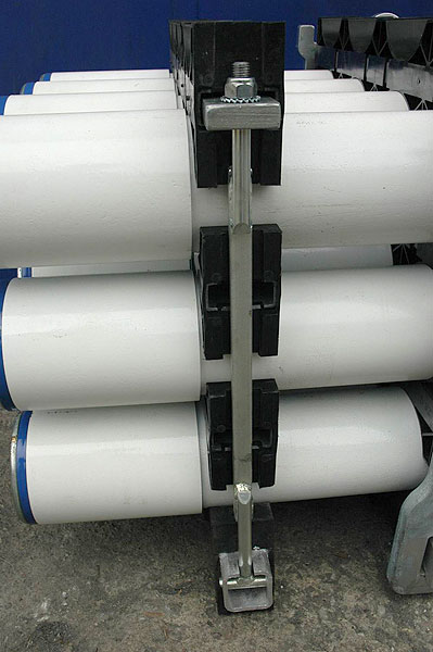
TF-LSGTF-LSG system enables to hoist the overall bundle by means of yokes by the crane, unless the necessity to pass the thru rope below such bundle. This is determined for safety pipe/tube bundle haulage of up to 7 t weight. Whole this system was designed such a way, to enable both maritime, oversea and railway shipment. The whole system consists of two central load bearing frames and two end type non-load bearing ones, which maintain the bundle shape and limit the pipe/tube bending in case of floor settlement. 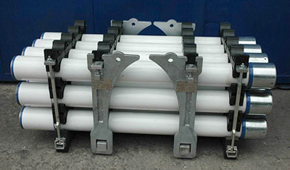 Simulation of pipe/tube bundle, consisting of 2 load bearing and 2 non-load bearing frames. Central Load Bearing Frame Consists of as Follows:
Support plates
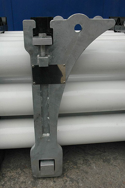
Load bearing frame of TF-LSG type
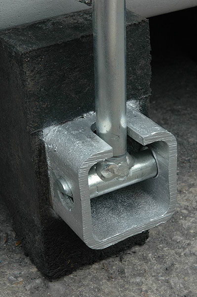
Bottom segment
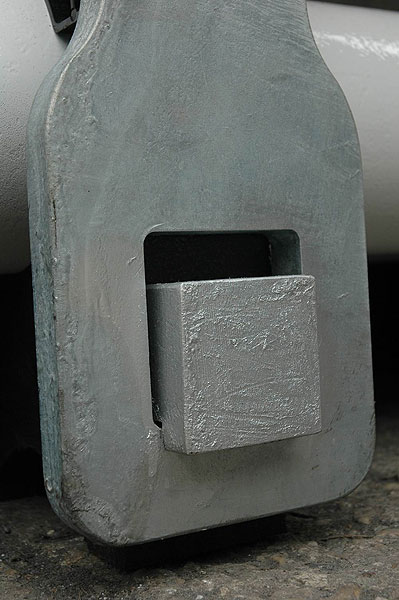
Bottom segment and its fixation in holes of the support plates
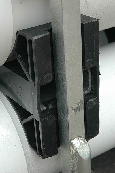
Intermediate segment
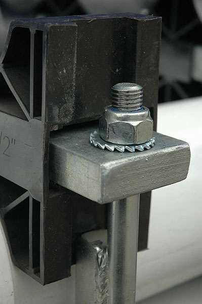
Ensuring the intermediate segments
Top segment
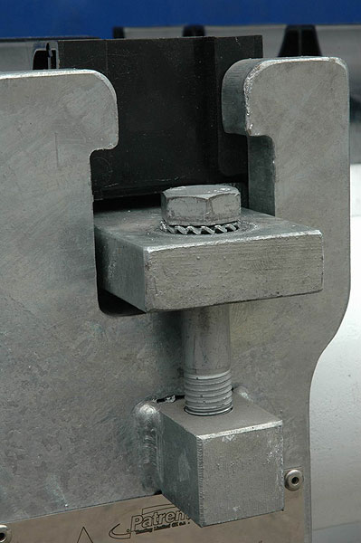
Top segment and its fixation to nuts located in support plates Boundary Non-load Bearing Frame Consists of as Follows:
Non-load bearing frame
Whole frame dragged with pull out rods
Bottom segment
Bottom segment and fixation of frame pull out rods
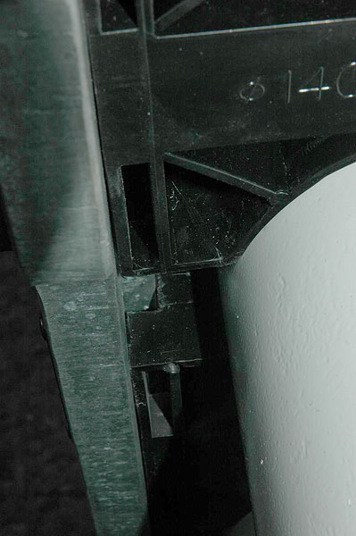
Intermediate segment
Intermediate segment fitted with a groove for guiding the pull out rods
Top segment
Top segment and screws of pull out rods
Transport frames of TF-LSG type are manufactured for following dimensions of pipes/tubes:
Storage Height and Loading of TF-LSGStorage height for pipe/tube bundles in case of application the transport frames of the TF-LSG system must be adapted to stability and loading capacity of the subsoil, haulage procedure, and the strength of bound pipes/tubes. Maximum load of the bottom segment within the frame is of 10 tons, that is why the load of pipe/tube bundle consisting of two load bearing and two non-load bearing frames must not exceed 40 tons. Testing of Load Bearing Frames of TF-LSGAll support elements of the TF-LSG - 2 frames consist of a support plate, together with the steel rod of the bottom segment - are tested and inspected from the safety reasons such a way, to meet international standards. Tested parts of the frame are marked with the label and confirmed thru the certificate. 
Labels confirming the testing of frames support parts. 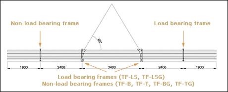
Testing of Load Bearing Frames of Both TF-LS and TF-LSG |